This academic project was carried out as part of a power electronics course and focused on understanding the fundamentals of Pulse Width Modulation (PWM) and its application to power inverters. PWM is a key technique used in modern electrical systems, particularly in motor control and power conversion, making it an essential concept for electrical engineering students.
The objective of this project was to study and analyze the behavior of voltage inverters controlled by PWM using MATLAB/Simulink and PSIM. The goal was to understand how different modulation strategies affect output voltage, current waveforms, and overall system performance through simulation.
With the results achieved, a concrete application was made with the implementation of a variable speed drive for three-phase asynchronous motor. The results are displayed using an oscilloscope to check the waveforms produced. The image shows the inverter used.
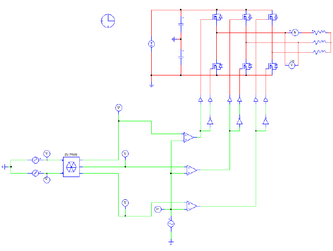
The work began with a theoretical analysis of single-phase and three-phase inverter structures, followed by the implementation of different PWM strategies, including two-level, three-level, and space vector modulation. Using PSIM and MATLAB/Simulink, the behavior of the inverters was simulated under various operating conditions to evaluate output voltage quality, harmonic distortion, and current behavior with different loads. The project concluded with the modeling of a complete variable speed drive for a three-phase induction motor, integrating rectification, DC filtering, and inverter stages, providing a global understanding of power conversion and motor control principles.
All detailed simulations, analyses, and results obtained during the project can be found in the full project report.